

WRITTEN BY KATE FINAN, CO-OWNER OF BOOM BOX POST
After buying our first home last year, my husband and I have been working hard at building our own home studio. In the past, every time we moved to a new apartment, we would always customize a home studio with our own DIY sound panels (see my blog post about that here). But since we plan to stay here forever, we have gone all out to make this studio space our own. And part of this customization has been soldering our own cables.
Why would you ever want to make your own custom cables? Doing so gives you the freedom to have cables that are the exact length that you want. You have the option to use top-notch components for less. And even when it doesn't save you money, it's a really fun way to get involved in putting together your studio. So, a better question may be: Why not?
This weekend, we tackled this endeavor, and we took plenty of photos to share.
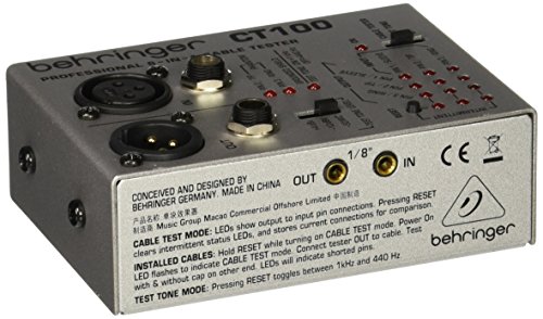
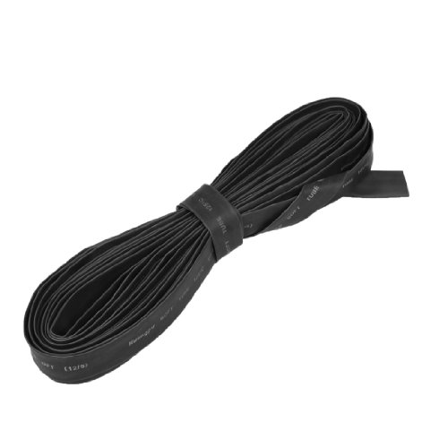
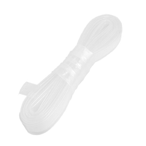
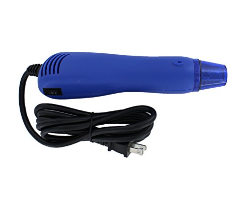
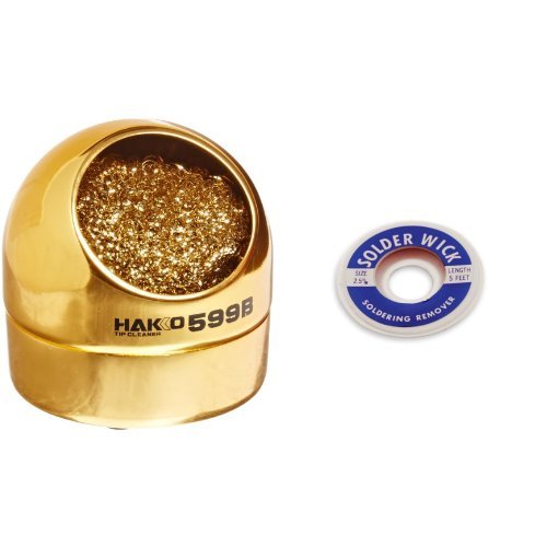
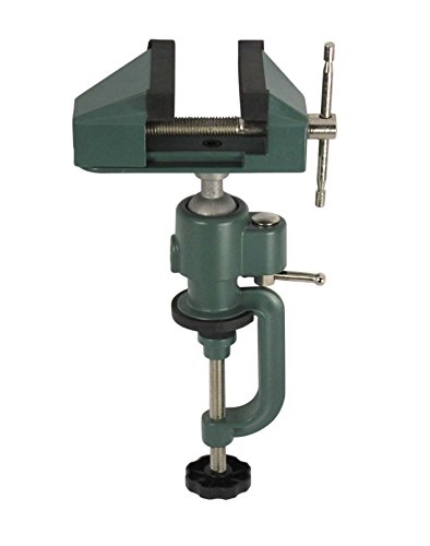
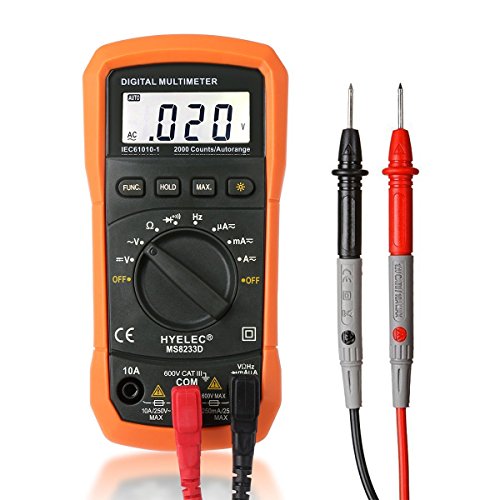
A few things to note: the heat shrink, both clear and black, and the heat gun are optional. The black heat shrink serves to create a stronger connection between the cable and the insert, and the clear plastic one is used for making custom labels. You can totally do without these steps if you're a novice and looking to save a little time and money. You can also do without the solder tip cleaner. We purchased this because it was only ten bucks and we were planning to make a number of cables. If you're just making one or two, it's not worth the investment. In this instance, we used a vice to hold our insert in place while soldering. You do not need a vice, specifically, but you do need something to hold your insert steady. We've found that the standard Helping Hands soldering arm can be a bit unwieldy. We like the vice because it has a strong grip and easily holds your insert firmly in a vertical position. And finally, you only need one way to test your cables out of the two options that I give below: the digital multimeter or the Beringer CT100. If you're new at this and plan to purchase one, definitely go with the Beringer. It's a lot more consumer-friendly and gives you the option to easily test lots of different cable types in the future.
Furthermore, please keep in mind that this is a DIY project that my husband and I undertook for fun. We enjoy having a home studio and have made it a hobby to learn new ways to make it our own. We have both soldered for years both at work and at home, but we are always honing our stills, and are my no means top-notch professionals at this particular task. That's why I run a post-sound studio, not a cable fabricating business! Do our cables always function? Yes. Do they look good? Yes. Am I selling my skills to top studios? Absolutely not. If you are already an expert, please feel free to comment with any tips, tricks, or suggestions on how to improve our process below!
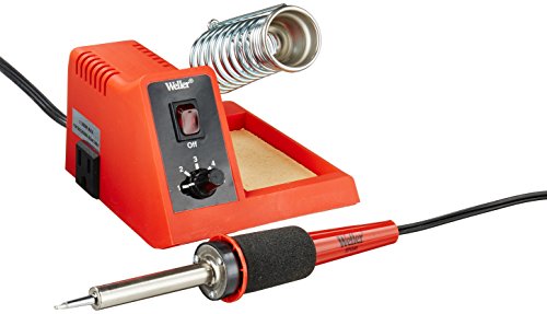
*Disclaimer: While this project is completely doable by your average home studio DIY'er, using a hot soldering iron is no joke. Be sure to read the instruction manual of your iron before attempting this, employ extreme caution, and if you've never soldered before, watch a few YouTube videos on soldering basics. Never touch the tip directly, and be careful to always place the soldering iron inside the stand between uses. Never place a hot soldering iron directly onto any other surface.
What You Need

Optional Supplies
Step-by-Step Instructions
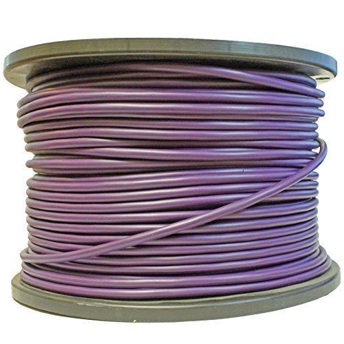
1. Insert the bushing over the raw cable. Then, insert the chuck onto the cable.

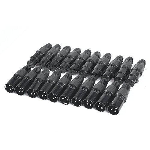
There are four parts to your XLR cable connector: the bushing, chuck, insert, and housing.
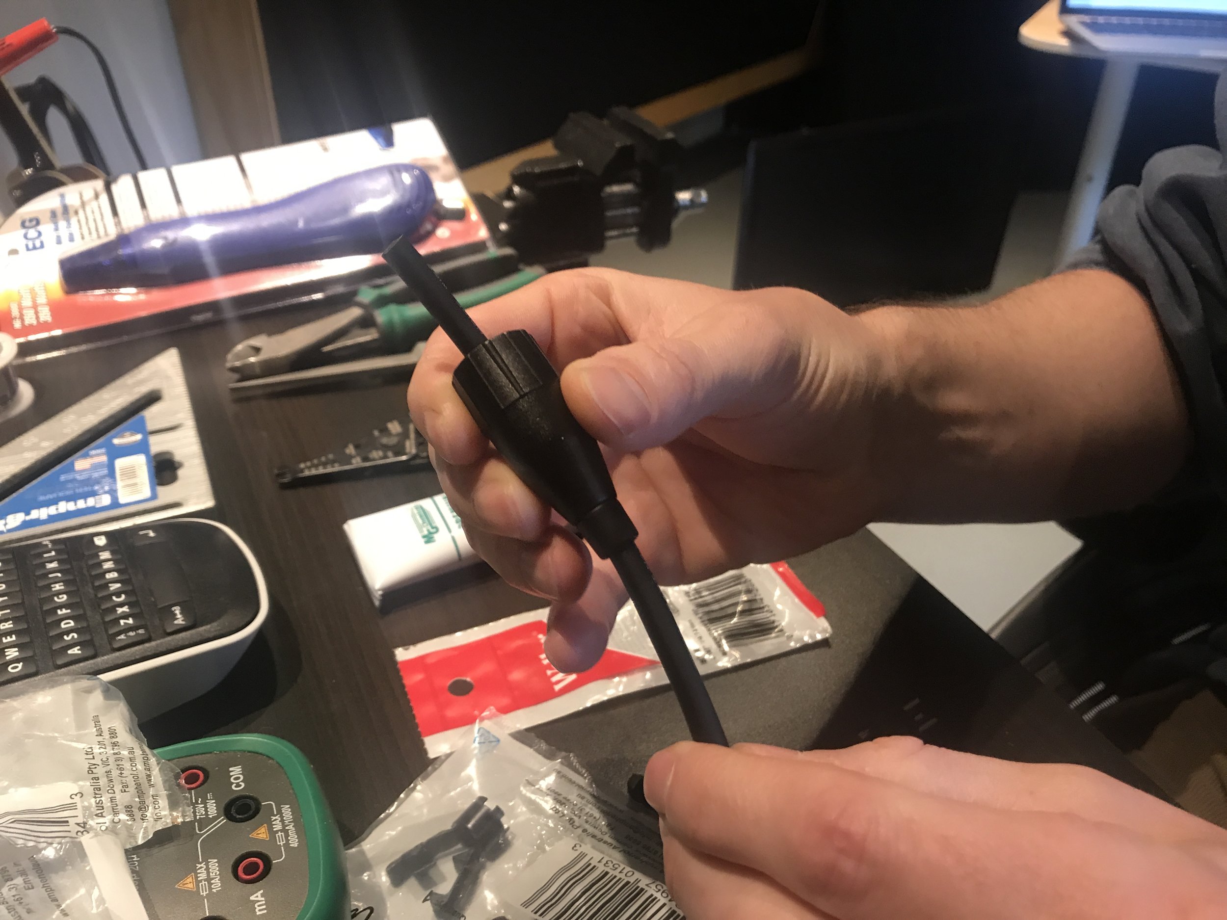
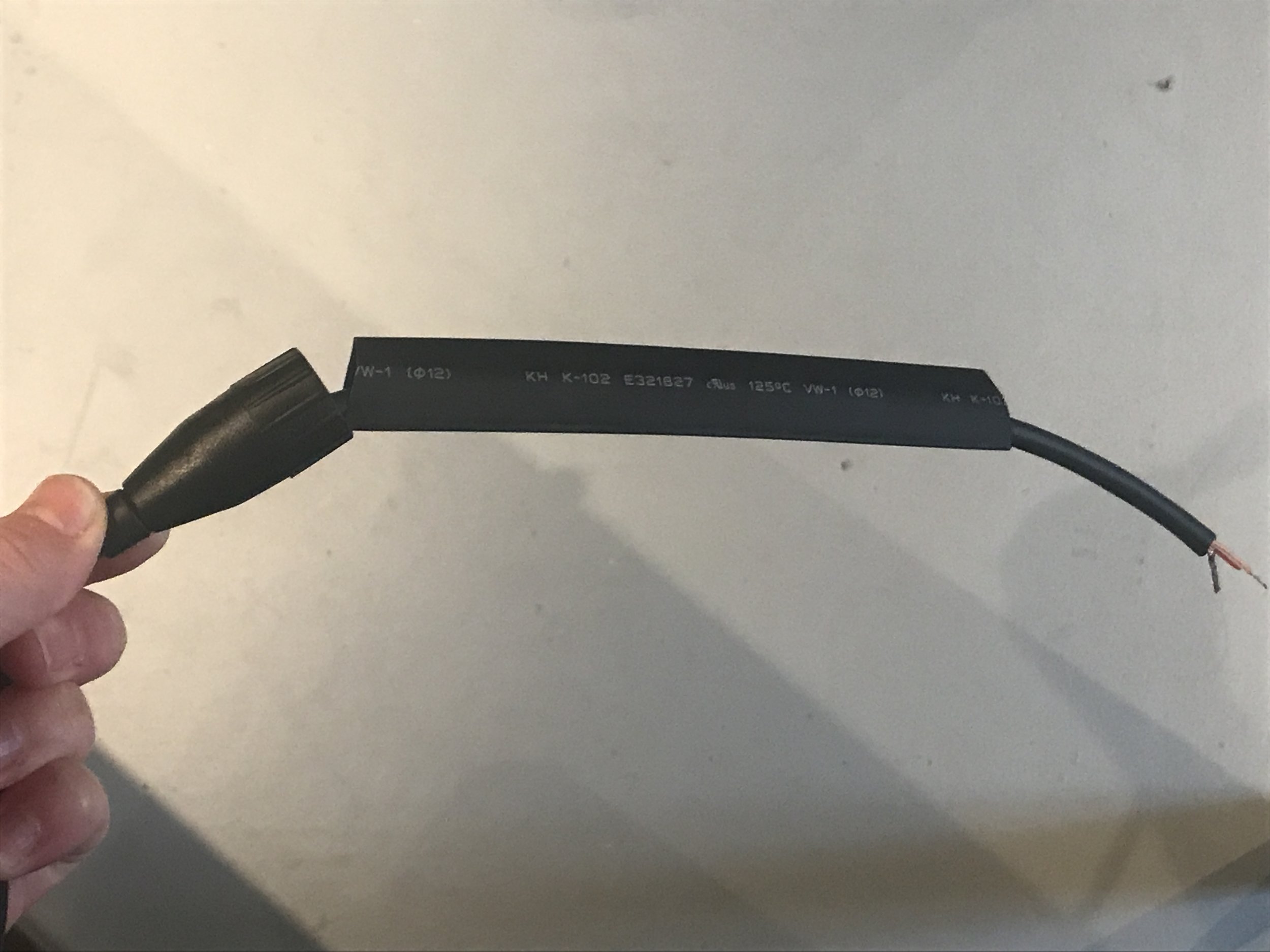
2. Cut a 6” piece of heat shrink material using scissors, and thread it over the raw cable after the bushing and chuck.

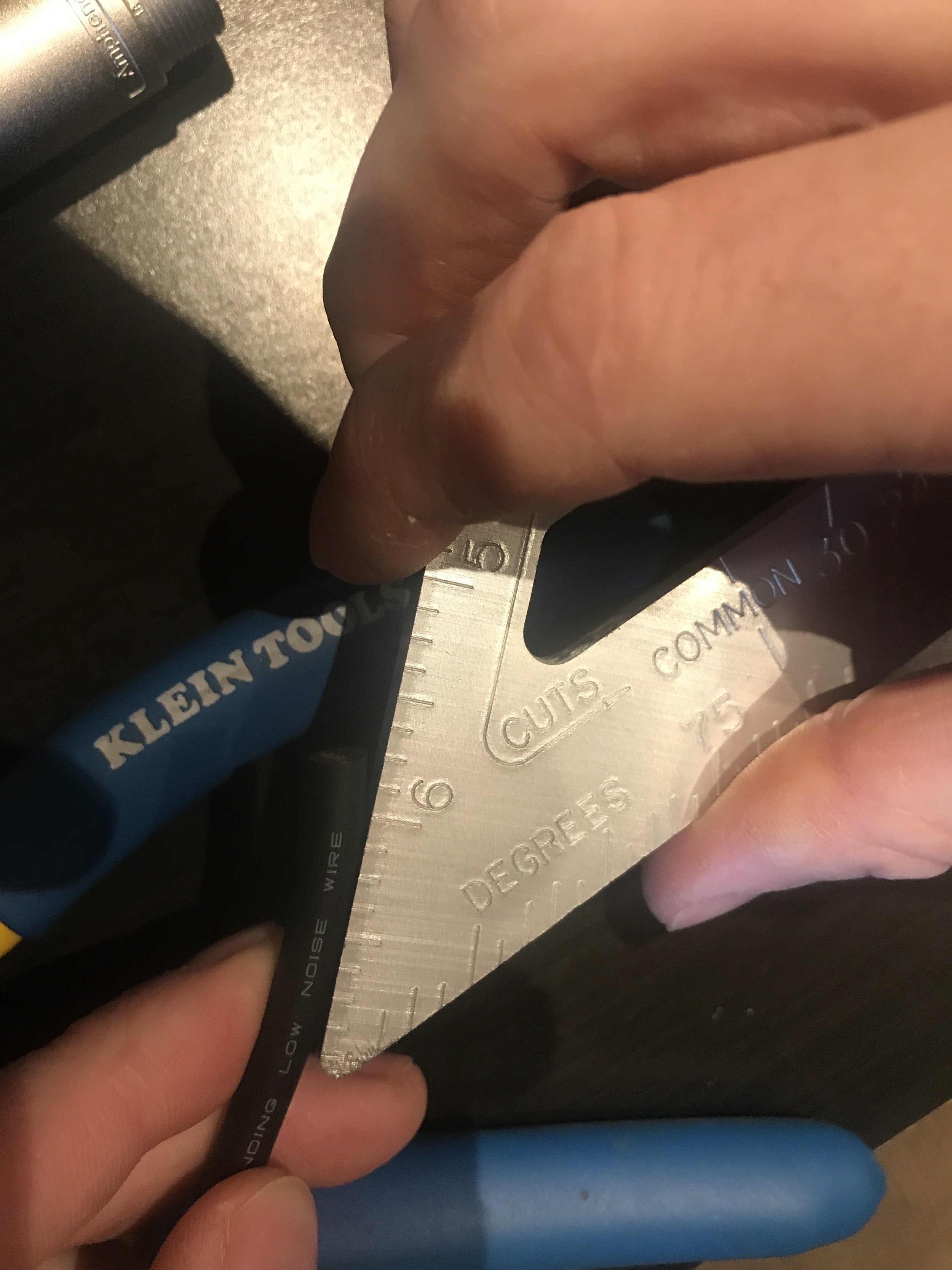
3. Score 1/2 “ on the cable. Then, use the sharp part of a cable stripper to strip off the rubber casing. (This picture shows us using a speed square, because that is what we had lying around at the moment. But, obviously, any ruler will do the trick.)


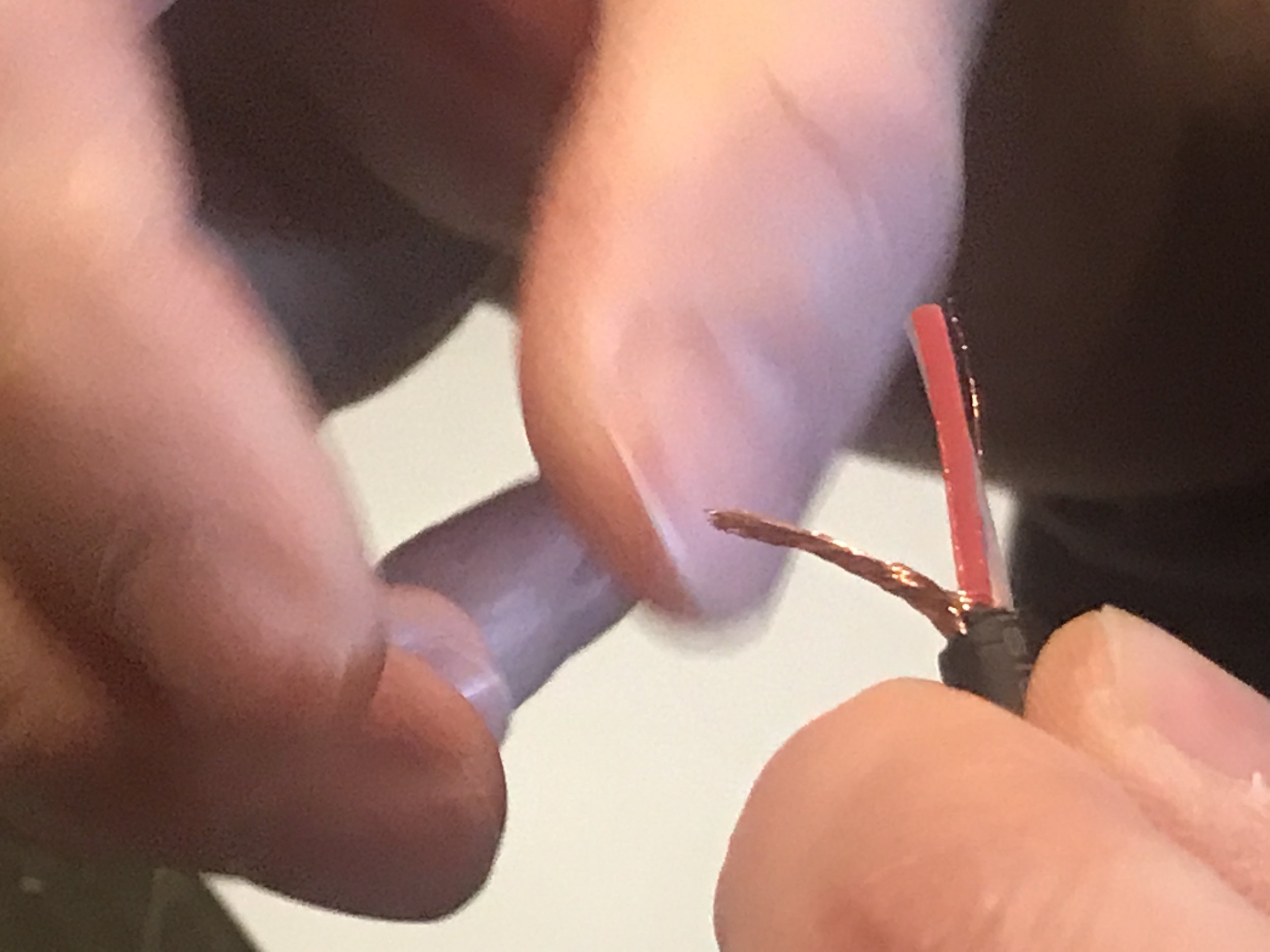
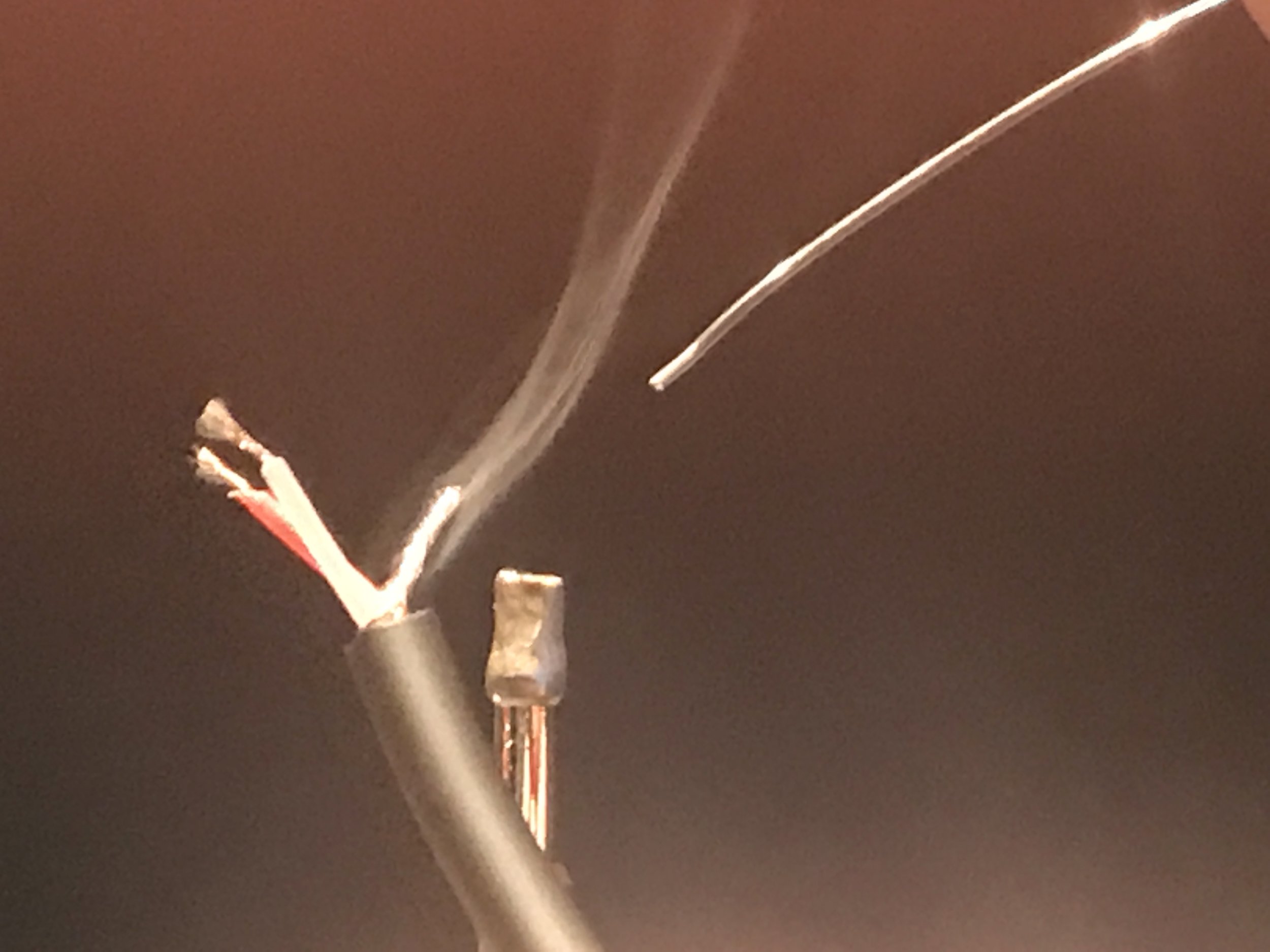
4. Separate the exposed copper wire from the red and white leads. This is the shield, or ground. Twist the copper wires that compose the shield together to create a single lead that can be soldered as one piece.

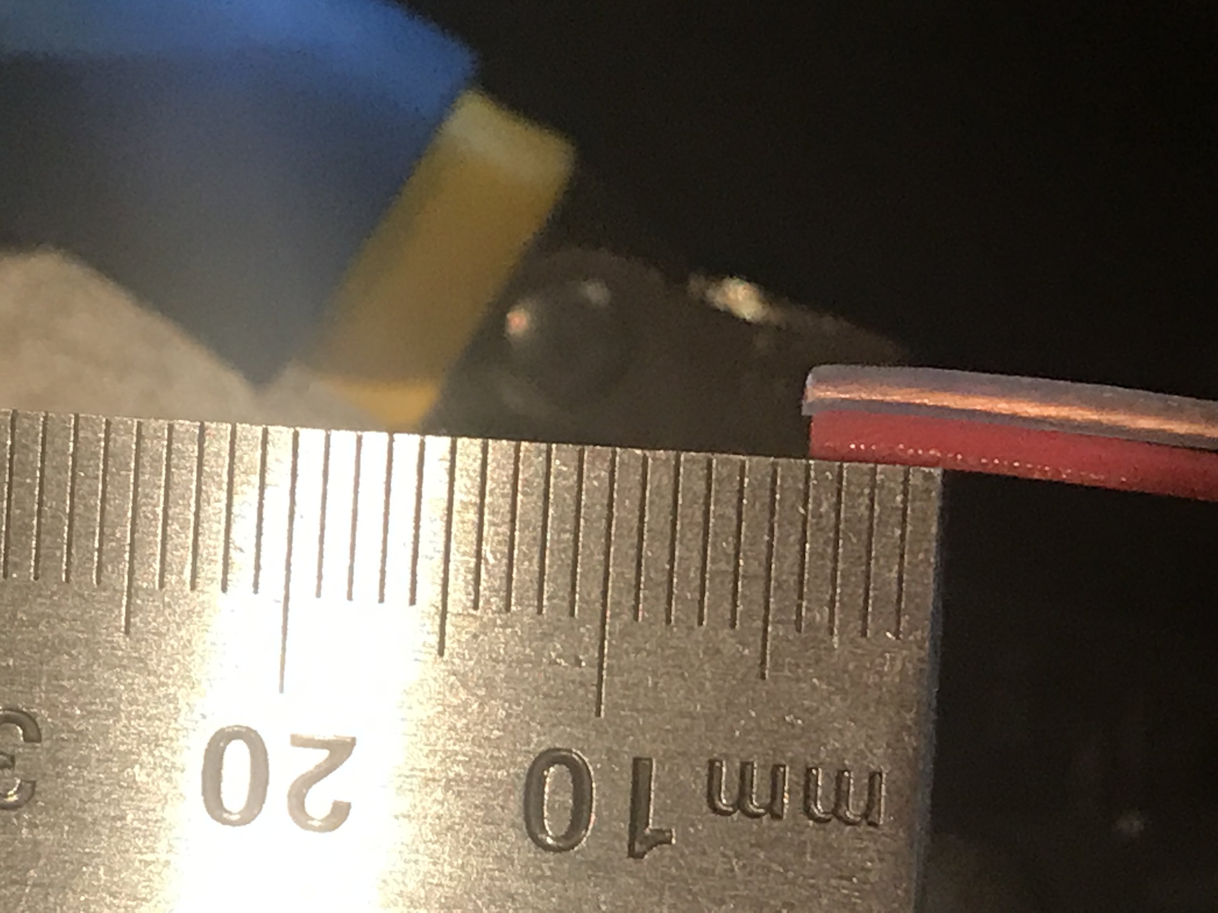
5. Strip 3mm off the red and white casings.

6. Twist the copper ends of each wire to make a tight connection wire.

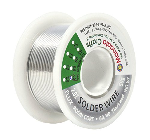
7. You want to tin each of the three wires. Tinning is the process of lightly coating a wire or partially filling a connector with solder so you can easily join the contact points. Tinning your wires first allows the solder to combine into the wire to unify it, making a better connection when you do join it to the other contact point.
Tin your connections by holding the soldering iron vertically in the vice. One at a time, hold the twisted tips of wire to the soldering iron and then drip a very small amount of solder onto each lead. Tin the full 3 mm of exposed wire with a very light and consistent coat of solder. Once cooled, remove the cable from the vice.


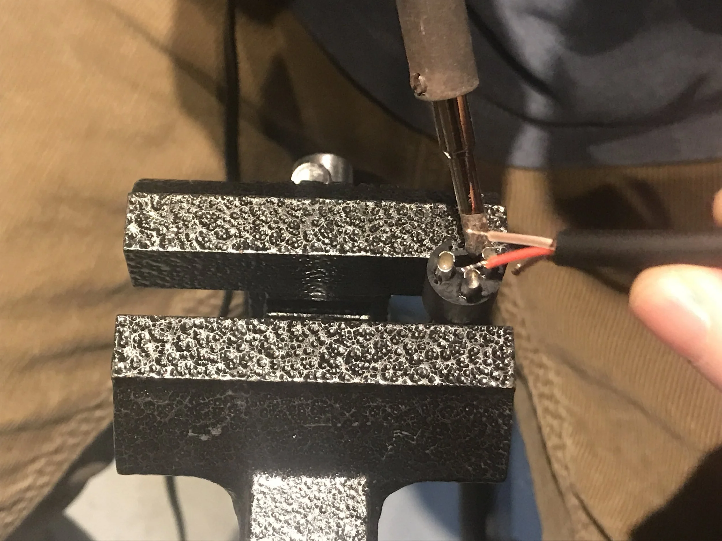
8. Place the XLR insert into the vice with the buckets pointing upward.

9. Clean the soldering iron tip to remove any excess solder left over from the tinning process.

10. Heat each bucket of the insert by placing the soldering iron against the side, then dip the edge of the solder into the bucket to fill it approximately half way.

11. Clean the soldering iron tip again to remove any excess solder.

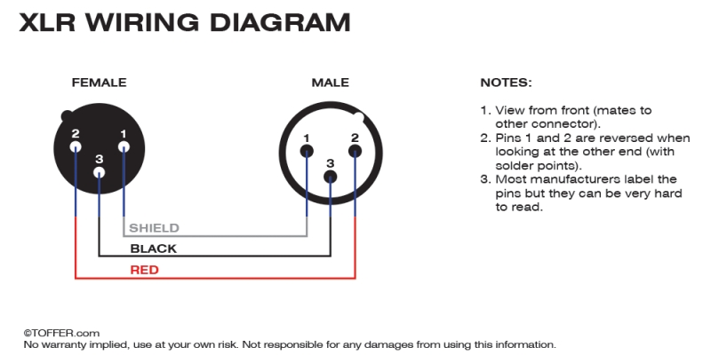
12. Connect each wire to the correct bucket. Each bucket should be labeled on the insert with the number 1, 2, or 3. The connections should be: Pin 1 = chassis ground (cable shield), Pin 2 = positive polarity terminal (hot), Pin 3 = Negative polarity terminal (cold). When viewing the diagrams below, note that the male is a mirror image of the female. Also, note that you should use a diagram oriented in the same way (rear view or front view) as you are viewing your cable insert.
Heat up the bucket, which will in turn hear the solder already inside. Do this by holding the soldering iron to the side of the bucket. Insert the wire into the bucket, remove the iron, and hold the wire in place until the pre-filled solder in the bucket cools.

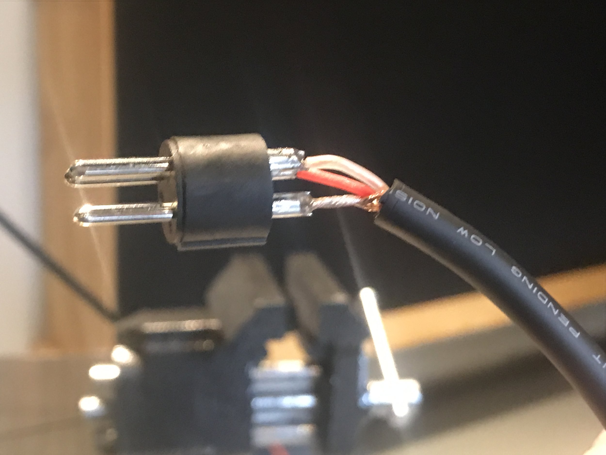
13. Check solder joints to make sure that you have not created any cold solder joints. A cold solder joint is undesirable in that it provides a very poor connection. It is easily identifiable by its coarse matte finish. A correct solder joint should have a shiny finish.

14. Also check that there is no no exposed copper wire after soldering. Wires should have been inserted into the bucket up to the casing. Exposed copper will cause a short.
15. On the other end of the cable, insert 6” of clear heat shrink material to use as a label guard, if desired.
16. Follow the above steps for the other side of the cable, paying close attention to the fact that the soldering connections will occur in the mirror image order between male and female inserts.
17. Turn the soldering iron off.
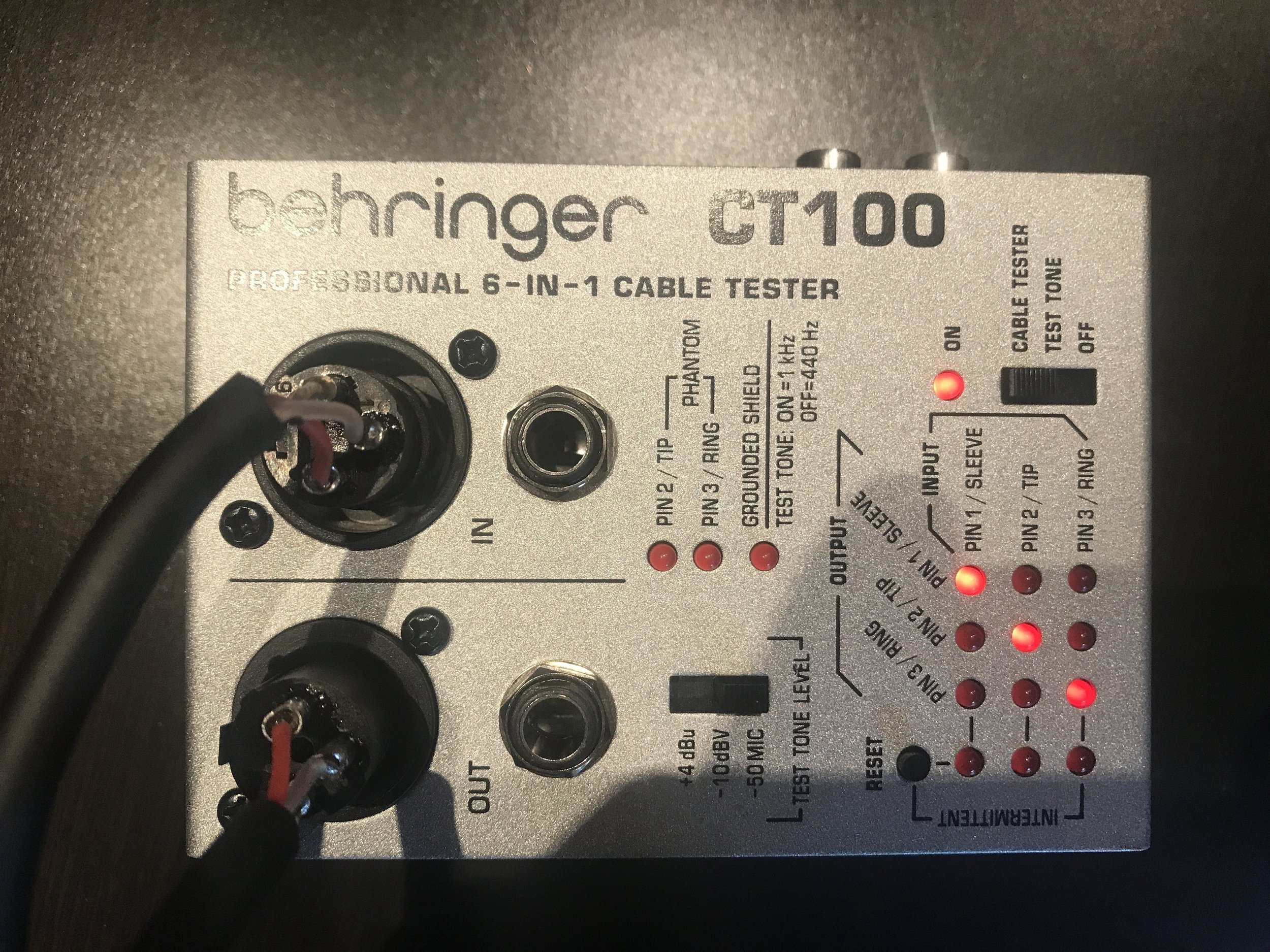
18. Use a cable tester to test your connections on each side. We use a Beringer CT100 6-in-1 Cable Tester. It tests all three pins on both sides of the cable at the same time. Plug in both ends, turn it on, set it to “cable tester”, and hit the reset button to be sure you get a fresh read. Make sure that each input pin is connected to the same output pin, and the connections are not intermittent.
19. Push the black heat shrink material down to be flush with the insert, covering the buckets, and turn on your heat shrink gun.

20. Point the heat shrink gun toward the heat shrink material, several inches away, and move it in a sweeping circular motion to shrink the material onto the cable. This heat shrink cover strengthens the end of the cable by creating a bond between the insert and the cable.


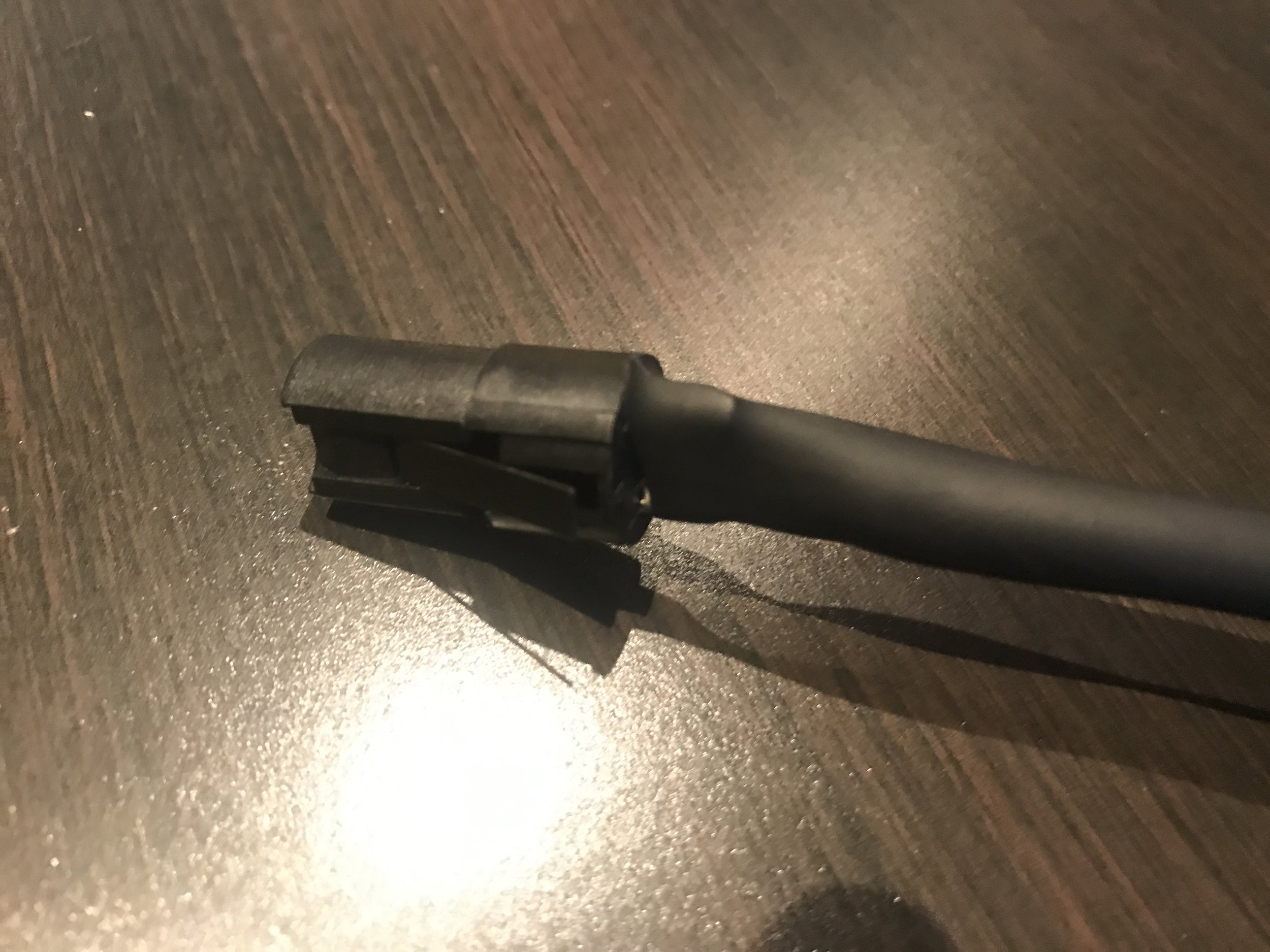
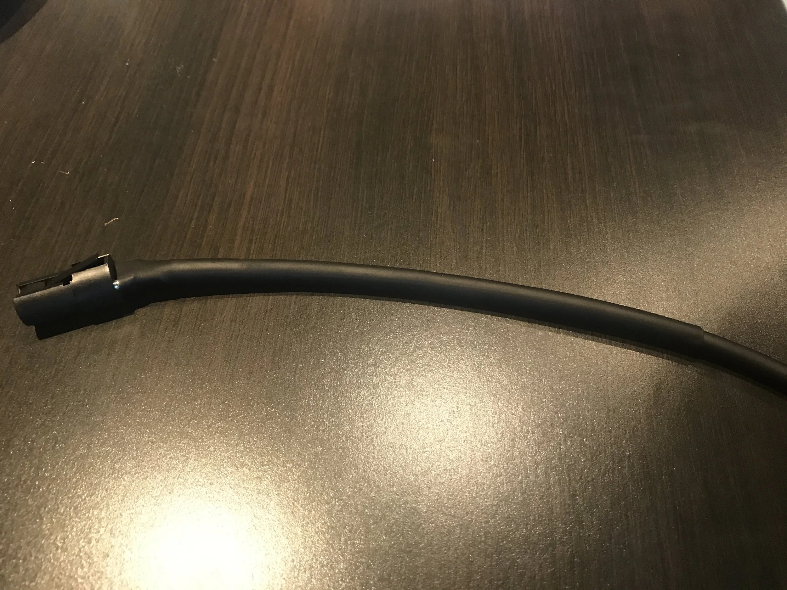
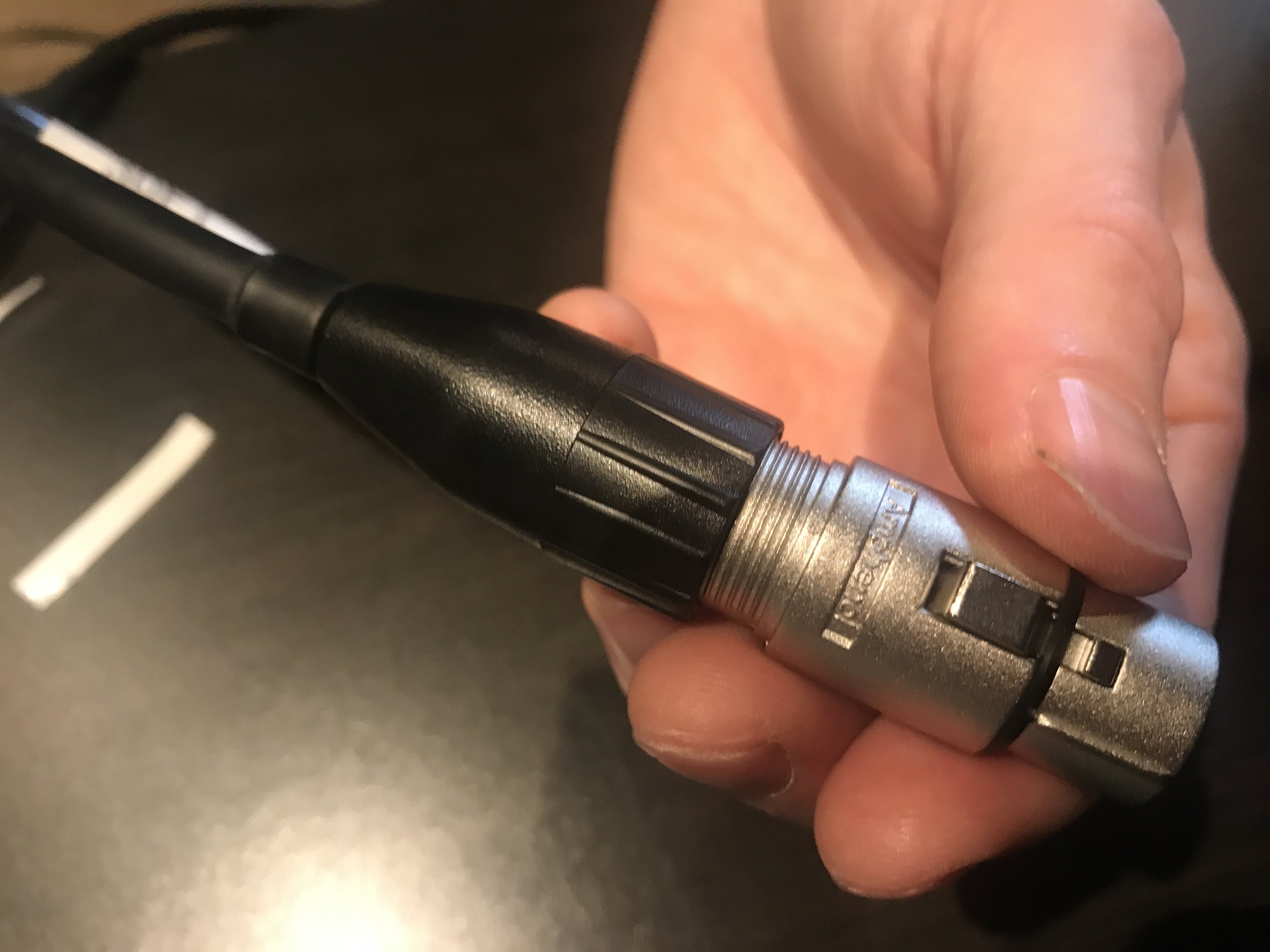
21. Insert the housing onto the end of the cable until it clicks into place over the insert. Thread the chuck and bushing over the heat shrink toward the insert, and screw the bushing into the housing, checking for a tight connection between all parts.
22. Follow steps 22 - 24 with the opposite end of the cable.
23. Create a label on your label maker, if desired, and attach it to the cable below the heat shrink material. Move the clear plastic heat shrink on top of the label, and use the heat shrink gun to affix the plastic on top of the label.


24. Test both ends of the cables again.

25. Alternatively (or additionally), you can test the cable with a digital multi-meter. Do this by setting your digital multi-meter to test tone, attaching the black lead to the COM connection, and the red lead to the Voltage Ohms jack. Then, touch the red and black leads of the cable to the same pin number on each end of the cable. If a complete path is detected, the digital multimeter will emit a tone.

26. Success! Your XLR cable is finished. Now, go have a beer!